Pkg Solutions
Quality Glossary
Drops and Shock Forces in Packaging
Shock is the force applied to a pack by a sudden change
in its velocity. This can be envisaged by a pack falling off the back
of a truck onto the sidewalk. The change in velocity, in that example
controlled by the distance fallen and the nature of the impacting surface,
indicates the severity of the shock felt by the pack and its product.
Shock is encountered in many areas of the distribution chain, not only
in simple drops but also in sudden stops and jolts due to the rigors of
transportation.
Drops
Drop tests are a common form of proving method for new
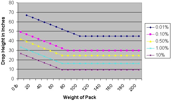
packs. Over many years a range of likely drop heights have been formulated
against particular pack weights. This is illustrated in the spreadsheet
below. As one would expect, lighter packs have a greater probability of
being dropped from a higher height. This is due to a number of factors,
such as their lighter weight making them more easy to be carried more
than one at a time. Light weight also makes packs more likely to be thrown.
Heavier parcels are more likely to be carried with greater care, to avoid
the worker injuring themselves, but rather than being placed on the floor
they can have a tendency to be dropped the final few inches to the ground.
Below are a few general observations:
Unitized loads are less likely to receive drops than single packs.
Packs often undergo a number of drops from lower heights, but the likelihood
of a pack being dropped more than once from three feet is low.
Light packs are likely to be carried in various orientations and so their attitude
when dropped can not be predicted.
Heavier packs have a 50% chance that they will be dropped onto their base.
Handholds reduce the chance of a high drop height by making the pack easier to lower
to the ground.
Labeling such as "Fragile" and "Handle with Care" does not
have a major impact in cutting damage.
Address labels tend to increase the chances of the pack being dropped with the
label uppermost.
The greatest damage to the pack results from corner or edge drops.
The greatest damage to the product occurs from drops onto the flat faces.
It is possible for shock to damage the product within a pack without appearing
to cause major damage to the pack. The normal solution to this is an improvement
to internal cushioning, rather than increasing the rigidity of the outer
pack.
The normal result of drops and shocks is damage, to
the pack this means that its protection and containment abilities are
reduced.
The chart below shows the percentage probability of
a particular drop height for a range of pack weights. Naturally this represents
only a generalization in relation to all possible distribution cycles.
The flat sections of the graphs represent where manual handling is likely
to be replaced by mechanical handling.
Shock Conditions
Shock can occur in the mechanical handling systems of
the distribution chain, but it is usually less server than the shocks
incurred in manual handling. Therefore any pack that has proved to be
sufficient in the manual handling section of a distribution chain will
usually be sufficient to survive normal mechanical handling. Abrasion
can occur in single packs during transportation as they move about. More
server damage may happen if the frequency of the transportation system
match the natural frequency of the product.
Parcel post and courier services provide a particularly
server test for a pack. The products are almost always below 40lbs in
weight and experience a great deal of manual handling, resulting in a
higher number of drops than average. Postal testing machines are available
to simulate these sever conditions and generally take the form of a large
wheel with steps inside.
Calculating a Product's Fragility Factor
One of the most frequently used ways to discover the
fragility of a product is to repeated drop samples and measure the drop
height at which damage starts to occur. However, quantifying fragility
as a drop height is useful only if no additional cushioning protection
is to be used in the pack. It is helpful for products that may experience
drops in their use environment, such as hand-held calculators, telephones,
and personal computers. It must be noted that without a knowledge of the
products fragility and areas of weakness it is impossible to calculate
an efficient cushioning system for a particular product. "G"
levels are commonly used to quantify an object's tendency to break when
subjected to a shock. The drop height used to determine the G level is
normally greater than probable drop height the packed product will experience.
An object will break if subjected to a force greater
than its structure can withstand. Force can be calculate from simple school
room physics:
Force = Mass X Acceleration
and deceleration are measures of the rate of change
of velocity and the forces in action are the same whether the object is
accelerating or decelerating; only the direction changes.
Once again school room physics reminds us that "G"
is the ratio of acceleration due to gravity to the observed acceleration:
     observed acceleration
G = -----------------------
     acceleration of gravity
If a 200g vase were dropped from one meter, at the moment
it reached the floor, its velocity would be 4.43 meters per second. If
on hitting the floor it lost this velocity (decelerated) in 0.002 second,
the deceleration could be calculated to be 2215 m/s2. Expressing this
as a ratio to normal gravity would give a G level of 226. At the moment
of impact, the vase would, in effect, weigh 226 times normal 45.2 Kg.
Unless it was a very unusual vase, breakage could be guaranteed.
If the vase were dropped onto a sponge rubber pad, the
impact velocity would remain the same. However, on impact the rubber pad
would deflect, and the time over which the cup lost velocity would be
extended. The deceleration would not be as severe and the stop not as
abrupt. If the vase now stopped in 0.008 second, the G level would be
56. Another sponge layer might increase the deceleration time to 0.01
second, and the vase would experience 45 G. Adding still more layers would
eventually reduce the G level to the point where the vase would not break.
This would be one way of determining what cushioning protection the vase
needed to protect it from a one meter drop.
However, if the G level that would break the vase was
known in advance, that is, if its fragility factor in Gs was known, it
would not be necessary to conduct the drop tests; the cushioning needed
could be determined by calculation. It can be seen from the vase example
that time is needed over which to dissipate the impact velocity and that
this time is gained by the deflection of a resilient cushioning material.
This is the basic principle of cushioning against shock.
An optimum cushioning material would provide constant
deceleration until it is totally compressed by 100% to a thickness of
zero. The thickness of cushioning (t) required to adequately retard an
object with a fragility factor of G. through a drop height (h), can be
expressed as:
      h
t = ---
      G
In reality, cushioning materials do not provide constant
deceleration, nor can they be compressed by 100% (60% is usually the maximum,
beyond which the material 'bottoms out'). Therefore the thickness of cushioning
required will always be greater than equation I shows, by a factor C,
which is specific for each type of cushioning material.
    Ch
t = --
     G
Where C is the cushion factor, a measure of a cushioning
material's efficiency as a shock absorber. Values of C for common cushioning
materials are shown in the table below
| Material |
Density kg/m3 |
Typical cushion factor |
Maximum static kPa |
Maximum stress kgf/cm2 |
| Flexible urethane foam + |
30 |
2.2 |
1.5 |
0.015 |
| Orientated rubberized hair: style CA |
96 |
2.4 |
9.8 |
0.1 |
| Orientated rubberized hair: style CA |
64 |
2.5 |
6.9 |
0.07 |
| Orientated rubberized hair: style CA/CA |
96 |
2.6 |
11.8 |
0.12 |
| Expanded polyethylene |
45 |
2.6 |
10.8 |
0.11 |
| Bonded polyurethane chipfoam |
64 |
3.0 |
1.8 |
0.018 |
| Bonded polyurethane chipfoam |
96 |
3.0 |
2.5 |
0.025 |
| Expanded polystyrene |
16 |
3.1 |
13.7 |
0.14 |
| Rubberized hair |
32 |
3.2 |
1.0 |
0.01 |
| Expanded polyethylene |
37 |
3.2 |
6.9 |
0.07 |
| Expanded ethylene vinyl acetate |
50 |
3.5 |
3.9 |
0.04 |
| Plain rubberized hair |
64 |
3.6 |
1.5 |
0.015 |
| Bonded polyurethane chipfoam |
144 |
3.7 |
5.9 |
0.06 |
| Bonded polyurethane chipfoam |
192 |
4.1 |
9.8 |
0.1 |
| Plain rubberized hair |
96 |
4.3 |
2.9 |
0.03 |
+ This material is likely to be more variable in performance
than other materials listed
Cushioning
Estimates of cushioning thickness can be made using
dynamic cushioning curves, these are available for most cushioning materials.
The information necessary to make these calculations using dynamic cushioning
curves is:
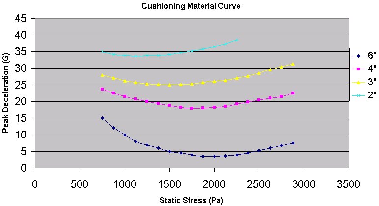
To use a dynamic cushioning curve (see the spreadsheet
above), locate the curve that crosses the desired critical acceleration
line twice. The required foam thickness and the acceptable static load
range can then be found. The two places where the critical acceleration
line is crossed represent the minimum and the maximum static loads. Usually,
a static load near the curve's minimum point would be chosen, but designing
with higher static loads would reduce cushion material area.
Understanding shock and fragility factors will help
to understand many shipping damages. For example, a refrigerator shipped
by road has a compressor motor assembly weighing 15 kilograms. The designer
felt safe in securing this assembly to the frame with three fasteners
capable of holding 120 kilograms, an ample safety factor. However, during
transportation, the refrigerator experiences a 10 G shock and, during
that brief moment, the motor behaves as if it had a mass of 150 kilograms.
Since the three mounting fasteners can hold only a total of 120 kilograms,
they may shear off. The refrigerator sidewall, with a bearing area of
1.5 square meters, and the shipping box are able to distribute the load
of a unit suddenly weighing 10 times more. With no external evidence of
damage, the refrigerator is accepted at the receiver's warehouse and by
the retailer. The problem is discovered only when a final customer plugs
it in.
Good manufacturers know the fragility factor for all
their products. In many instances, they will redesign products with low
G levels, knowing that the saving in protective materials, and the goodwill
generated by satisfied customers, will more than repay the cost of added
engineering. Fragility may be greatly dependent on how the force is transmitted
to the product. An egg on a flat surface has a fragility of 35 to 50 G.
depending on the axis of impact. If the egg is supported in a conforming
surface, its fragility can exceed 150 G
Below are some examples of fragility factor classes.
A manufacturer would be advised to consider redesign of any product with
a fragility level of less than about 30 G.
|
G Factor
|
Classed as
|
Examples
|
| 15-25 G
|
Extremely fragile
|
Precision instruments, first-generation computer hard drives |
|
25-40 G
|
Fragile
|
Benchtop and floor-standing instrumentation and
electronics
|
|
40-60 G
|
Stable
|
Cash registers, office equipment, desktop computers
|
|
60 - 85 G
|
Durable
|
Television sets, appliances, printers
|
|
85-110 G
|
Rugged
|
Machinery, durable appliances, power supplies, monitors
|
|
110 G
|
Portable
|
Laptop computers, optical readers
|
|
150 G
|
Hand held
|
Calculators, telephones, microphones, radios
|
It should be noted that the explanations for shock provided
in this web page are simplified. Proper consideration of shock and shock
protection takes into account not only peak G but also velocity change.
These two factors are usually represented by a "damage boundary curve."
The proper method of quantifying shock fragility is through the use of
a shock test machine. This device is capable of providing a shock pulse
of an accurately defined amplitude, duration, and shape.
Cushioning Against Shock
Any material that will deflect under an applied load
can act as a cushioning material. By deforming, the cushioning material
reduces the peak G level experienced by the product, compared to the shock
pulse felt at the package surface.
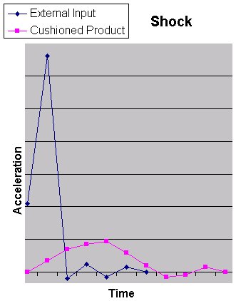 |
A cushioning material
reduces the initial shock force at the pack's surface so that the product's
response takes place over a longer period of time. The areas under the
curve represent energy. |
The choice of cushioning materials will be into three
main types: Cellulosics, Polymerics, and Long Fibers, such as animal hair
bonded with rubber materials and wood wool. Shredded paper, Tissue paper,
Corrugated board and molded pulp are examples of cellulose cushioning
materials, which can be the most economical. However, such materials may
not be as suitable from an abrasive and cleanliness point of view. They
can also react corrosively with certain products. Alternatively, molded
shapes, from materials such as EPS can prove expensive to produce in anything
but high volumes. Loose foam chips are usually a more economical alternative
for low quantities.
Polymeric materials can be produced in a wide range
of resiliency's and densities. Expanded Polystyrene (EPS), Foam polyurethane
and air bubble sheet are examples of polymeric materials. These materials
can be more suitable from a cleanliness point of view. Cushioning polymers
are not hygroscopic; however, some open-celled foams like polyurethane
can absorb liquid when wet.
Loose fill cushioning material are particularly useful
for odd shaped products, but can settle in transit. In some cases loose
fill cushioning materials can be recovered for reuse. In response to environmental
issues, loose fills based on recycled corrugated cases are being used.
Foam-in-place polyurethane is labor-intensive in a packing process, but
is another versatile cushioning material, enabling custom shapes to be
easily produced.
Preshipment Testing Equipment
Vibration Tables
Vibration tables are used to assess product and package responses to the various ranges of
vibration that they will experience in the field. They are available in two basic types:
Repetitive-shock vibration tables operate at about 1.1 G (acceleration), 1-inch amplitude,
and 4.5 hertz. These tables are used in tests specified by the Dangerous Goods Code and in
procedures recommended by the ISTA and by ASTM D 4169. They are also useful for determining
relative scuff resistance.
Variable-frequency vibration tables are programmable to sweep through all common transport
frequencies between 3 and 100 hertz. They can be more realistic in representing the true
distribution environment. They are also used to search out resonance weaknesses in the
unpackaged product and to locate stack resonance points for stacked packages.
The following vibration tests are described by the ASTM:
- D 999, Vibration Testing of Shipping Containers
- D 1185, Pallets and Related Structures Employed in Materials Handling and Shipping.
- D 3580, Vibration (Vertical Sinusoidal) Test of Products
- D 4782, Random Vibration Testing of Shipping Containers
- D 5112, Vibration (Horizontal Linear Sinusoidal Motion) Test of Unpacks_ Products and Components
- D 4169, Performance Testing of Shipping Containers and Systems Drop Testers
The principal feature of all drop-test devices is the ability to produce rep drops at selected
orientations and from selected heights without imparting roation or other influences. Drop heights
can be selected from drop probability tables, from standards set by the ISTA or ASTM, or by the
requirement of a danger,: hazardous goods code.
Drop tests are described in the following standards:
- ASTM D 5276, Drop Test of Loaded Containers by Free Fall
- ASTM D 1083, Mechanical Handling of Unitized Loads, Large Shipping Cases and Crates
- ASTM D 3071, Drop Test of Glass Aerosol Bottles
- ASTM D 5487, Standard Practice for Simulated Drop Tests of Loaded Containers by Shock Machines
- ASTM D 5265, Bridge Impact Testing
Horizontal and Incline (Conbur) Impact Machines
The incline impact machine simulates horizontal shocks such as those expeerienced¬ rail shipment. The shock can
be controlled by changing the impact velocir by using impact programmers. By using suitable backloads during the
effects of dynamic horizontal compression can also be assessed. With modifications, the incline impact machine is
also used to determine the durability of pallets to repeated forklift entries.
Incline impact tests are specified by ISTA and ASTM preshipment test meth- ods and are described in the following:
- ASTM D 880, Incline Impact Test for Shipping Containers
- ASTM D 1185, Pallets and Related Structures Employed in Handling and Shipping
- ASTM D 4169, Performance Testing of Shipping Containers and Systems
A newer, more controllable method of producing horizontal shocks is horizontal impact machines. These machines
accelerate the load along a horizontal track and into a programmable backstop.
- ASTM D 4003, Programmable Horizontal Impact Testing for Shipping Containers and Systems
- ASTM D 5277, Performing Horizontal Impacts Using an Inclined Impact Tester
Good packaging laboratories are able to provide a wide range of climatic conditions with environmental chambers. They are typically used for preconditioning prior to physical testing. For example, to determine the ability of a plastic pail to survive drops at subzero temperatures or to identify whether a corrugated box loses stack strength at high humidity, both packages would require preconditioning in the appropriate environment.
Such chambers are also used to accelerate aging for such things as long-term storage tests and for environmental stress-crack tests on plastic containers (ASTM D 2561, Environmental Stress-Crack Resistance of Blow-Molded Polyethylene Containers).
All standard paper tests should be conducted at 23 ± 2°C and 50% R.H. ± 2%. The highest humidity normally recommended for routine testing is 85%. Beyond this humidity, it becomes very difficult to control the temperature with the accuracy needed to prevent condensation. To simulate a particular environmental condition, the conditions listed in Table 16.4 are the normal choices.
Environmental conditioning is described in
- ASTM E 171, Standard Atmospheres for Conditioning and Testing Materials
- ASTM D 685, Conditioning Paper and Paper Products for Testing
- ASTM D 4332, Conditioning Containers, Packages or Packaging Components for Testing
Compression Test Systems
Compression strength is directly related to warehouse stacking ability. A compression test system is used to
determine the load-carrying abilities of a package. Sizes vary from small, for measuring the compression strength
of plastic bottles, to units large enough to measure the stack strength of entire pallet loads. Fixed-platen
testers tend to cause the specimen to fail at its strongest point. Swivel platens tend to cause the specimen
to fail at its weakest point.
Compression tests can be either dynamic, using hydraulically or mechanically driven platforms, or static,
wherein a dead load is stacked on a subject containerand the system observed over a period of time. Compression
tests are required by most preshipment test procedures and are described in:
- ASTM D 642, Compression Test for Shipping Containers
- ASTM D 2659, Column Crush Properties of Blown Thermoplastic Containers
- ASTM D 4577, Compression Testing of Shipping Containers Under Con Load
Recommended standard atmospheric conditions as provided in ASTM D 4332.
| Simulated Environment |
Temperature |
Relative Humidity |
| Cryogenic | -55 ± 3°C | - |
| Frozen food storage | -18 ± 2°C | - |
| Refrigerated storage | 5 ± 2°C | 85 ± 5% |
| Temperate,humid | 20 ± 4°C | 85 ± 5% |
| Tropical | 40 ± 2°C | 85 ± 5% |
| Dessert | 60 ± 3°C | 15 ± 2% |
Shock Machines
Shock machines are used to develop fragility boundary curves and to determine G
levels used in calculating cushioning requirements or for assessing a product's design fragility.
A shock machine consists of a rigid table that can be raised and dropped onto a programming device.
By controlling the programming device and the drop height, different G levels, pulse durations, and
pulse shapes (sine, square wave, etc.) can be achieved.
Tests using shock machines are described in the following:
- ASTM D 3332, Mechanical Shock Fragility of Products Using Shock Machines
- ASTM D 4168, Transmitted Shock Characteristics of Foam-in-Place Cushioning Materials
- ASTM D 5487, Standard Practice for Simulated Drop Tests of Loaded Containers by Shock Machines
ISTA and ASTM Preshipment Testing Procedures
In the late 1940s the Porcelain Enamel Institute's members were experiencing considerable shipping damage.
They conducted studies to identify a standard shipment test procedure that would assess the protective
characteristics of packaging. A requisite was that damage created in the lab should closely duplicate that
observed in the field. The procedure that was developed was found to be usefu other industries and soon
was widely adopted.
Modified and updated under the sponsorship of ISTA, these test methods continue to be used today. Briefly,
in the Project 1 A procedure, the package is Subjected to 14,200 (11,200 if the package is over 60 pounds)
vibratory impacts on a vibration table operating at about 1.1 G and 4.5 hertz. Subsequently, the package is
dropped 10 times from a height related to the package weight and in specified orientations. (See Table below).
Packages over 61 pounds may optionally be tested on an incline impact machine, as described in Project 1 for
products weighing over 100 pounds.
The ISTA also describes static and dynamic compression tests and recomended tests for export packaging in
Projects 2 and 2a. Project 3 is proposed the overnight overnight shipping environment. Incline impact and
climatic tests are required by some procedures, particularly for heavy products.
ISTA methods are quick, economical, and simple. However, as knowledge the shipping environment increased,
drawbacks became apparent. Damage cannot be duplicated by the ISTA methods is commonly observed. Another
short-coming is that shipping vibrations in the real world are not fixed at 4.5 hertz. ISTA data have limited
use for package design inputs.
Drop heights and orientations for ISTA preshipment tests.
| Package Weight |
Drop Height |
Drop Number |
Orientation |
| 1 through 20.99 pounds |
30 inches |
1 |
2-3-5 corner* |
| 21 through 40.99 pounds | 24 inches | 2 | Shortest edge leading out from that corner |
| 41 through 60.99 pounds | 18 inches | 3 | Next shortest edge from that corner |
| 61 to 100.00 pounds | 12 inches | 4 | Longest edge from that corner |
| | 5 and 6 | Fiat on one of the smallest faces and on opposite small face |
| | 7 and 8 | Flat on a medium face and on opposite medium face |
| | 9 and 10 | Flat on one largest face and flat on opposite large face |
*The convention for identifying the faces of a package is to place the package in its stable shipping
position and to face the end with the manufacturer's joint. Call the top 1, the right side 2, the bottom 3,
and the left side 4. The near end is 5 and the far end is 6.
In response to a need for a more flexible preshipment testing methodology, the ASTM published a new
standard preshipment testing procedure, ASTM D 4169, Practice for Performance Testing of Shipping Containers
and Systems.
The ASTM method recognizes that different distribution elements impose different hazards on the product
and package. (See Table) It further recognizes that different products might require different levels
of assurance against product damage. The ASTM procedure essentially outlines the elements needed to tailor
a preshipment test procedure to a specific need.
Summary of ASTM D 4169 distribution testing elements.
| Shipping Element |
Hazard |
| Element A: Manual handling up to 90.7 kg | Drop |
| Element B: Mechanical handling over 45.4 kg | Rotational drop |
| Element C: Warehouse stacking | Static load |
| Element D: Vehicle stacking | Static load |
| Element E: Vehicle transport, unitized load | Vibration |
| Element F: Loose load vibration | Repetitive shock |
| Element G: Vehicle vibration | Vibration |
| Element H: Rail switching | Horizontal impact |
| Element I: Climate, Atmospheric condition | Temperature and humidity |
| Element J: Environmental hazard | Similar to military specification MIL-P-116 |
To use the procedure, you first identify the nature of the distribution environment you wish to
simulate in the laboratory and what the shipping unit will be for different stages of the journey.
In the ASTM procedure, unlike the ISTA, tests done on the actual unit being shipped, which may vary at
different points distribution. For example, a unit load may constitute the test unit for part of the
gram, and an individual container may be used for the remainder.
The elements representing the identified shipping environment and the a: priate assurance level are
then selected from the test method. A decision as to constitutes an unacceptable level of damage must
be made. The test procedure describes different shipping modes, or elements, and provides for introducing
atmospheric factors at any point in the test program.
The entire sequential test would be performed when evaluating a new shipping container. Where the package
response to a single condition might be needed, only that element needs to be performed. The operator has
the option of designing a custom sequence or using one of the 18 predesigned sequences describing most
common distribution cycles.
The ASTM procedure is able to simulate more of the hazards encountered in distribution, and in a more
realistic way than the ISTA methods. ASTM dures also provide valuable design information. However,
establishing a tory capable of performing the ASTM D 4169 tests is more costly orders of magnitude than
for ISTA, and skilled operators are required to tests and interpret data. There is also some contention
regarding the select:: sequences and their levels. Further, not all shipping problems need the
sophistication of the ASTM D 4169 approach.
Preshipment testing is a valuable tool in the development of a suitable bution package or for resolving
specific problems. Whatever tests are chosen the damage observed in the laboratory should be similar in
appearance observed in the field. One fallacy that must be avoided is that a particular time or exposure
in the laboratory is equal to a certain number of kilometers or miles in the field. Finally, it should be
understood that the ultimate and true test is a successful shipping history.
Other Test Methods and Standard Practices
The following are selected other standards related to packaging materials.
- ASTM D 6198, Standard Guide for Transport Package Design
- ASTM D 4649, Selection of Stretch, Shrink, and Net Wrap Materials
- ASTM D 5118, Fabrication of Fiberboard Shipping Boxes
- ASTM D 5168, Fabrication and Closure of Triple Wall Corrugated Fib Containers
- ASTM D 4919, Testing of Hazardous Materials Packaging
- ASTM D 3951, Commercial Packaging
- ASTM D 1974, Methods of Closing, Sealing, and Reinforcing Fiberboard Boxes